How to Build a Raspberry Pi Kubernetes Cluster
Intro
For years I’ve been fascinated by the idea of running my own home lab as a way of learning more about cloud architecture. That might seem ironic if you know my history with deploying software on Azure and AWS, but there are a few advantages to running the hardware (and the infrastructure software, for that matter) myself. I have more control over the hardware, I get actual experience maintaining and understanding the hardware and the infrastructure software, and I can’t accidentally incur massive cloud fees because of configuration mistake. So I’ve made my own cloud, in my own house, with Kubernetes running on a cluster of Raspberry Pis (or Raspberries Pi?), with the help of a bunch of existing setup guides and K3S. And I’ve named it us-east-1, because I’ve already joked for years that I have us-east-1 under my desk and that I’m personally at fault every time it goes down.
The Parts
- Raspberry Pi 4 8GB (4) — The physical nodes of my cluster
- Raspberry Pi PoE+ HAT (4) — Hats extend the functionality of Raspberry Pis. The PoE+ Hat allows me to power the device through ethernet, so I don’t need extra power cables
- 4 & 40 Pin Extra Tall header (Push Fit Version) - POE HAT Set (4) — Because the PoE+ Hat covers the 40 pin connector on the Raspberry Pi, I’m using these to extend the pins through the hat so I can still use them for connecting to the fans
- 2x2 pin, 2.54mm Double Row Female Straight Header (4) — Works better than the 4 Pin Extra Tall header from the Extra Tall header set, which has really long pins that are easy to bend
- A Brass Standoff Screw Nut Assortment bundle — Various standoffs to hold the Raspberry Pi boards up from the mounts and to secure the hats to the Raspberry Pis
- C4Labs Cloudlet CASE: Cluster Case for Raspberry Pi and other Single Board Computers — A number of folks make these cases. This one can take 8 Pis but with the hats it can only fit 4, which is perfect for me
- 50mm 5V cooling fan (4) — Little fans for attaching to the case to cool the Pis
- 8 Port gigabit PoE Switch with 2 Gigabit uplink — I bought a STEAMEMO unmanaged PoE switch
- Monoprice Cat6A Ethernet Patch Cable (10-pack) — To connect all the things
- 32 GB Micro-SD cards (4) — To hold the operating systems for each Pi and on-board storage
Preparing the SD Cards
Before moving on to building the cluster, I loaded the SD cards with operating systems so the Pis were ready to run before I plugged them in.
- Get the Raspberry Pi Imager from the Raspberry Pi software page. https://www.raspberrypi.com/software/
- Follow the Install using Imager steps from Raspberry Pi. I personally used the Raspberry Pi OS, and I have read guides suggesting Ubuntu, so I know both work, but other options might work too.
- In the Customisation section of the Imager, make sure to enable SSH. I used password authentication, but public key authentication will also work for our purposes.
- (Optional) Also in the Customisation section, my nodes have wi-fi capability so I set them up to connect to my router. My setup with an unmanaged switch allows direct access via ethernet anyway, so it wasn’t necessary (the technical bit is that the router’s DHCP functionality automatically assigns them to IPs, though I am hard-coding static IPs long-term).
- (Optional) Still in the Customisation section, I chose a hostname for each of my nodes, which is unique on my network. I use this hostname to log into each node using SSH instead of having to figure out what the IP address of each node is.
- Finish writing the image to each SD card before moving on to the next section.
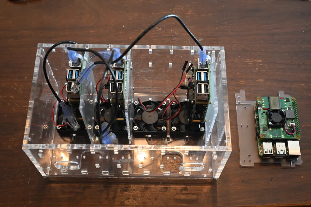
The Build
Building the cluster was pretty straightforward since I am used to building my own computers, though it would be a bit nervy if I had never done it before. They are just plug-and-play components though, so they are quite forgiving and there is no soldering or wilder stuff involved.

- Attach the Raspberry Pi to the plastic rack from the cluster case. I used a screw with a small brass ring spacer between the plastic and the Raspberry Pi board. It could actually be installed on either side of the rack, so I had to make sure to install all of the Pis on the same sides of their racks.
- My screws weren’t actually screwed into anything at this point, so I screwed in my brass standoffs on the other side of the Raspberry Pi. I had to test a bit to find the right height standoff to go with the extra tall headers.
- Install the extra tall header on the 40-pin array, being careful not to bend the pins on the Pi or on the header.
- Install the extra tall header on the 4-pin array, again begin careful not to bend the pins on the Pi or the header. (I messed this up once and had to troubleshoot)
- Now that I had the spacers and the extra tall headers in place, I put the PoE+ hat on the Raspberry Pi. I threaded the pins from the 40-pin array through the holes and made sure that the 4-pin array was cleanly connected to the PoE+ hat.
- Repeat the same for all of the other Raspberry Pis
- Screw the fans into each of the slots of the Cloudlet CASE
- Slide the Pis into the Cloudlet Case on their racks. I did this one-by-one with the next step, as it can get hard to access the wires and the pins if all of the Pis are installed.

- Connect the fans with the pins of the Raspberry Pis. I have thus far not needed full-powered fans for my cooling needs, so I plugged the red wires plugged into a 3.3V power pin (1) and the black wires plugged into a ground pin (6). If I couldn’t separate the wires I would have used the 5V pin (4) next to the ground pin (6), which would have been noisier but is technically the right voltage for these fans. For more guidance on Raspberry Pi pinouts I used this resource (https://pinout.xyz/)
- I had room so I slid the Network Switch into the case resting on top of the racks. Then I plugged in its power cable and connected it to my router.
- Install the prepared Micro SD cards into the Raspberry Pis
- Plug the Raspberry Pis into the Network Switch via ethernet. Because of the PoE+ hats, this also powered up the Pis.
Getting Started on K3S
What is K3S
Way back in 2018, the folks at Rancher Labs recognized a need for a smaller version of Kubernetes. Kubernetes is typically abbreviated as K8S (K, 8 letters, then S), so a half-sized version would be K3S; hence the name. The folks at Rancher eventually figured out that there’s widespread general demand for Kubernetes on resources-constrained environments, so they forked K3S out of its parent project (Rio) and donated it to the Cloud Native Computing Foundation (CNCF). It’s a supremely easy-to-install version of Kubernetes that is optimized for ARM architecture, making it the perfect choice for this build.
Installing K3S on the Server Node
In K3S, to run a cluster I needed to have a Server Node that contains the control-plane and datastore components and Agent Nodes that do not contain these components (K3S can run in a multi server cluster but that’s beyond the scope of this piece).
To install K3S on the server node, I logged into the node using SSH and ran the following command:
curl -sfL https://get.k3s.io | sh - I verified my install using the kubectl get node command:
sudo k3s kubectl get node This returns a list of nodes in the cluster, which was just this node at the moment.
I left this terminal window open because I had some more things to do with the server node.
Installing K3S on the Client Nodes
I added new client nodes by running the same curl command that installed the server node, except with a K3S_URL pointing to my server node and a K3S_TOKEN generated by the server.
I got the K3S_TOKEN by using the following command on my server node:
sudo cat /var/lib/rancher/k3s/server/node-tokenThen, I SSH’ed into each of the agent nodes and installed K3S using the following command:
curl -sfL https://get.k3s.io | K3S_URL=https://<SERVER_IP>:6443 K3S_TOKEN=<K3S_TOKEN> sh -Installing K3S tools on the dev machine
So that I don’t have to SSH into the server node to manage my cluster, I installed K3S tools on all of my dev machines so that I can directly control the cluster from afar. I used the Kubernetes CLI, kubectl, which gives CLI access to the entire Kubernetes Control Plane API. I also installed kubens (now part of kubectx) to make it easier to switch between namespaces instead of appending the namespace to every kubectl command.
Kubernetes publishes an install guide for their command line tools here: https://kubernetes.io/docs/tasks/tools/#kubectl. I installed kubectl using Homebrew on Mac and Chocolatey on Windows, as package managers can make it easier to keep these tools up to date. Because my Mac has Homebrew installed and my Windows machine has Chocolatey installed, installed these using the following commands:
On Mac
brew install kubectl
brew install kubectx
On Windows
choco install kubernetes-cli
choco install kubens kubectx
Once I had kubectl installed, I copied the kubeconfig file from the server node to my dev machines in order to use kubectl on the dev machines to interact with my cluster, using the following command to print the kubeconfig:
sudo cat /etc/rancher/k3s/k3s.yamlOn the dev machines, I replaced the existing files at ~/.kube/config with this file.
Monitoring my cluster
While kubectl gives a bunch of control of the cluster and really can tell me anything I need to know about what is going on, it presents a rather steep learning curve to understanding Kubernetes. What could really help complement that full control is a top-level view, which I am doing using a dashboard application installed directly in the cluster. Basically all of the guides I’ve previously followed suggested monitoring the cluster using Kubernetes Dashboard. However, delving back into home cluster configuration in the last week of January in 2026 presented somewhat of a problem: Kubernetes Dashboard was retired on January 21, 2026! It can still be used (https://github.com/kubernetes-retired/dashboard), but as the maintainers have noted, the project is now archived due to lack of active maintainers and contributors. I took their suggestion and installed Headlamp instead.
Installing Headlamp is a perfect opportunity to get familiar with Helm (https://helm.sh/), a package manager for Kubernetes that I had previously used in my work life to deploy applications to EKS (Elastic Kubernetes Service, the AWS-hosted version of Kubernetes). It’s probably the most straightforward way to deploy most major applications to a cluster.
I prefer to install Helm using Homebrew in Mac or Chocolatey in Windows:
Installing Helm
On Mac
brew install helmOn Windows
choco install kubernetes-helmInstalling Headlamp
I installed Headlamp using the Helm instructions in Headlamp’s In-cluster instructions (https://headlamp.dev/docs/latest/installation/in-cluster/#using-helm). Specifically, this is what I did, as reproduced from the above link in January of 2026:
# first add Headlamp's custom repo to your local helm repositories
helm repo add headlamp https://kubernetes-sigs.github.io/headlamp/

# now you should be able to install headlamp via helm
helm install my-headlamp headlamp/headlamp --namespace kube-system
Accessing the Headlamp dashboard
I am still learning about Ingress about this point (I will be posting about this soon) so to make things easier I used port forwarding to expose the headlamp end point to my localhost:
kubectl port-forward -n kube-system service/my-headlamp 8080:80I could now navigate to the headlamp dashboard for my cluster at http://localhost:8080/
Headlamp either accepts a token or an OIDC login. I’ve gone with a service account with a token for now, though I will write a follow-up if I switch to OIDC. Headlamp provides instructions for creating a service account and generating a token here: https://headlamp.dev/docs/latest/installation/#create-a-service-account-token. I’ve reproduced the commands below:
# create a service account called headlamp-admin
kubectl -n kube-system create serviceaccount headlamp-admin

# give admin rights to this account
kubectl create clusterrolebinding headlamp-admin --serviceaccount=kube-system:headlamp-admin --clusterrole=cluster-admin

# generate a long-lived token for local access
kubectl create token headlamp-admin -n kube-system --duration=8760h
Next Steps
My plans for my own home lab can be split up into two categories: maintaining the infrastructure (hopefully through automation) and deploying projects for personal use and experimentation.
For maintaining infrastructure:
- Automating OS updates and upgrades for the nodes using Ansible or Puppet
- Automating K3S upgrades using
system-upgrade-controlleror other tools - Installing a continuous delivery tool like ArgoCD
For personal projects and experiments to deploy on Kubernetes:
- Deploy Jellyfin for personal media streaming
- Deploy Immich for self-hosted Photo and Video backup
- Deploy a local instance of Amazon DynamoDB
Other resources
I encourage you to look at this guide as one way of getting up and running with Kubernetes in a home lab, and to explore the other options for more ideas and more opionions on how to go about it. Here are a few that have been helpful to me:
- My Kubernetes Homelab project https://medium.com/@ilankushnir/kws-cluster-e7e079cf103b
- Ilhan Kushnir describes his home lab, complete with an integrated RPi NAS Server
- Building a bare-metal Kubernetes cluster on Raspberry Pi https://anthonynsimon.com/blog/kubernetes-cluster-raspberry-pi/
- Anthony Simon describes a similar project to mine, except he uses a separate router between his main router and the network switch. He also uses kubernetes dashboard, which is deprecated in favor of Headlamp, and uses NGINX as Ingress, which is deprecated in favor of Traefik (which comes with K3S anyway)
- Part 1: Running a Kubernetes Cluster on Raspberry Pi with k3s: Cheap, Low Power, Fully Functional https://calje.medium.com/running-a-kubernetes-cluster-on-raspberry-pi-with-k3s-cheap-low-power-fully-functional-9e2cc50ba64f
- Lucas Calje has a full series on his own homelab project, with a number of ideas for next steps
- Step-by-Step Guide: Creating a Kubernetes Cluster on Raspberry Pi 5 with K3s https://www.everythingdevops.dev/blog/step-by-step-guide-creating-a-kubernetes-cluster-on-raspberry-pi-5-with-k3s
- Chinaza Otumba goes into a lot more detail about using the Raspberry Pi Imager; if you’re stuck on this part, this is a good resource
Comments
No comments yet. Be the first to reply on Bluesky!